Introduction to Programmable Logic Controller and Ladder Logic
Contents:
The are very useful devices and still play a major role in industrial automation for a more in-depth lesson on electromechanical relays check out this post. In the first programmable logic controller came along to replace complicated relay circuitry in industrial plants. The PLC was designed to be easily programmable by plant engineers and technicians that were already familiar with relay logic and control schematics. Since the beginning PLCs have been programmable using ladder logic which was designed to mimic control circuit schematics.
The ladder diagrams look like control circuits where power is flowing from left to right through closed contacts to energize a relay coil.
- Programmable Logic Controllers (PLC)!
- Worst Case Bioethics: Death, Disaster, and Public Health!
- ?
- Die Frauen und das Netz: Angebote und Nutzung aus Genderperspektive (German Edition)!
- A Prairie Prayer;
As you can see, ladder logic looks like simple control circuit schematics where input sources like switches, push-buttons, proximity sensors, etc are shown on the left and output sources are shown on the right. The ability to program complicated automated processes with an intuitive interface like ladder logic made the transition from relay logic to PLCs much simpler for many in the industry. Although, the first PLCs were very limited in their memory and speed capabilities, they quickly improved over the years. The presence of PLCs helped simplify the design and implementation of industrial automation.
PLCs can be described as small industrial computers with modular components designed to automate control processes. PLCs are the controllers behind almost all modern industrial automation.
A Beginner’s PLC Overview, Part 1 of 4: Introduction to PLCs
There are many components to a PLC, but most of them can be put in the following three categories:. PLCs are complex and powerful computers. But, we can describe the function of a PLC in simple terms. We will get into more detail later but for now, think of it like this:. Many dishwashers have microprocessors that function similarly to PLCs.
The dishwasher has inputs, outputs and, of course, a CPU. Some of the inputs into the dishwasher controller would be the buttons on the front, the water sensors and the door switch. Some of the dishwasher outputs would be the water valves, the heat elements and the pumps. Remember, the CPU is the processor in the dishwasher that is programmed to make all the decisions we will see below.
In the the dishwasher example above, we treated every input and output as a discrete or digital signal. Discrete signals are signals that can only be on or off.
We will cover this in more detail in part 3 of this series. The term was first coined by the market research firm ARC in to differentiate the original PLCs from the newer, more powerful, more flexible controllers that were entering the market. There is disagreement about the definition differences between PAC and PLC, and often the terms are used interchangeably in the industry. I often use the terms interchangeably myself. In my opinion PACs are always the better choice unless the system is very simple and minimizing cost of the project is vital.
Navigation menu
Personally, I think this is a great move. Thus, an industrial electrician or electrical engineer accustomed to reading ladder logic schematics would feel comfortable programming a PLC to perform the same control functions. PLCs are industrial computers, and as such their input and output signals are typically volts AC, just like the electromechanical control relays they were designed to replace.
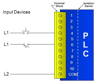
Although some PLCs have the ability to input and output low-level DC voltage signals of the magnitude used in logic gate circuits, this is the exception and not the rule. The following illustration shows a simple PLC, as it might appear from a front view. In this way, the PLC is able to interface with real-world devices such as switches and solenoids.
The actual logic of the control system is established inside the PLC by means of a computer program. This program dictates which output gets energized under which input conditions. Although the program itself appears to be a ladder logic diagram, with switch and relay symbols, there are no actual switch contacts or relay coils operating inside the PLC to create the logical relationships between input and output.
These are imaginary contacts and coils, if you will. When the pushbutton switch is unactuated unpressed , no power is sent to the X1 input of the PLC. They do not exist as real electrical components.
They exist as commands in a computer program—a piece of software only—that just happens to resemble a real relay schematic diagram. Once a program has been loaded to the PLC from the personal computer, the personal computer may be unplugged from the PLC, and the PLC will continue to follow the programmed commands. The true power and versatility of a PLC is revealed when we want to alter the behavior of a control system.
Since the PLC is a programmable device, we can alter its behavior by changing the commands we give it, without having to reconfigure the electrical components connected to it.
- Featured Products.
- .
- The Unwanted.
For example, suppose we wanted to make this switch-and-lamp circuit function in an inverted fashion: In the following illustration, we have the altered system shown in the state where the pushbutton is unactuated not being pressed:. One of the advantages of implementing logical control in software rather than in hardware is that input signals can be re-used as many times in the program as is necessary. For example, take the following circuit and program, designed to energize the lamp if at least two of the three pushbutton switches are simultaneously actuated:.
Introduction to Programmable Logic Controllers - Part I - a PDH Online Course for Engineers
To build an equivalent circuit using electromechanical relays, three relays with two normally-open contacts each would have to be used, to provide two contacts per input switch. Take for instance this next system, a motor start-stop control circuit:. An important point to make here is that fail-safe design is just as important in PLC-controlled systems as it is in electromechanical relay-controlled systems. One should always consider the effects of failed open wiring on the device or devices being controlled.
In this motor control circuit example, we have a problem: So, we see there is no operational difference between this new design and the previous design. The result, then, for a wiring failure on the X2 input is that the motor will immediately shut off.
In this circuit, the lamp will remain lit so long as any of the pushbuttons remain unactuated unpressed. To make the lamp turn off, we will have to actuate press all three switches, like this:. This section on programmable logic controllers illustrates just a small sample of their capabilities. As computers, PLCs can perform timing functions for the equivalent of time-delay relays , drum sequencing, and other advanced functions with far greater accuracy and reliability than what is possible using electromechanical logic devices.
- Sagt Supermäh zu Spidermäh: Die 444 besten Kinderwitze (German Edition)
- Brogans Seed: Like a Brother
- Treatment Plans and Interventions for Depression and Anxiety Disorders, 2e: Treatment Plans and Interventions for Evidence-Bas
- Learning Disabilities: Practice Concerns and Students with LD: 25 (Advances in Special Education)
- Prisoner B-3087
- Securing the Clicks Network Security in the Age of Social Media