Logic Synthesis for FSM-Based Control Units: 53 (Lecture Notes in Electrical Engineering)
Contents:
Journal of Circuits, Systems, and Computers 26 7: CloudBus protocol hardware multi-converter gateway for distributed embedded systems.
Lecture Notes in Electrical Engineering Logic Synthesis for FSM-Based Control Units But as a rule, control units have an irregular structure which makes. Lecture Notes Electrical Engineering Volume 53 Alexander Barkalov and Larysa TitarenkoLogic Synthesis for FSM-Based.
Designing Moore FSM with extended class codes. Journal of Circuits, Systems, and Computers 23 6 Design of Moore finite state machine with coding space stretching. Journal of Circuits, Systems, and Computers 22 3 Compositional microprogram control unit with operational automaton of transitions.
Hardware reduction for compositional microprogram control unit dedicated for CPLD systems.
Design of moore finite state machine with extended state codes. Design of microprogrammed controllers to be implemented in FPGAs. In this article the method is proposed permitting mutual area decrease for both blocks of FSM.
One of Moore FSM features is existence of pseudoequivalent states [2], which are the states with the same transitions by the effect of the same inputs. Such states correspond to the control algorithm operator vertices [1], outputs of which are connected with an input of the same vertex.
Refine list
Let us code set Yq with binary code K Yq having Ry bits, where. Let us use the following relation a on this set E1.
Let us encode each vertex bq e Cj by the binary code K bq having. In this case, the code for state am e A can be represented as:. Each function Bi e B is represented as the following. The matrix M6 implements the input memory functions. The matrix M8 implements functions yn e Y, depending on terms Aq e Yo.
Field-programmable gate array
There are some positive features in the proposed method. Now codes of collections of microoperations do not depend on state codes.
In , the Naval Surface Warfare Center funded an experiment proposed by Steve Casselman to develop a computer that would implement , reprogrammable gates. Their values are calculated as some Boolean functions depending on the values of operands. Lecture Notes in Computer Science. Microprogram control units were very popular in the past [1,12,13,16,19,24,27, 38, 41, 43, 52, 55, 58, 60, 64], but they have one serious disadvantage, namely inferior performance in comparison with the equivalent finite state machines. Sign in to annotate.
The number of rows. It allows such their encoding that diminishes the area occupied by BIMF. As it was mentioned, it is enough. The main drawback of U2 is increase of the number of inputs for BIMF if the following condition is true:. Besides, the model U2 includes the block BCT, which requires some area of the chip.
The method includes the next stages:. For the first step implementation the known method [1] is used, when every operator vertex is marked by a unique state.
Synthesis of FSMs Based on Architectural Decomposition with Joined Multiple Encoding
Remind, that states am, as e A are named pseudoequivalent, if marked by them operator vertices of GSA are connected with the input of the same vertex. The main goal of the third step is maximum decrease for the number of terms in system Y0. In the best case, each microoperation yn e Y is represented by a single term and the matrix M 8 is absent [1]. The fourth step is executed on the base of 5.
The codes of states am e A are determined using the formula 7. The last step is discussed in the proposed example. Let us encode the collections Yq c Y as it is shown in Fig. There is the following system 8 in our example:.
- Navigation menu.
- Post navigation.
- Leb wohl, Schlaraffenland: Die Kunst des Weglassens (German Edition)!
- Women Deacons: Past, Present, Future;
This system together with state codes from Fig. This table is used to derive the system For example, the following functions can be found from Table In the case of matrix implementation, there is no need in minimizing these functions.
The Journal of Committee of Electronics and Telecommunications of Polish Academy of Sciences
The table for BCT is absent on our example because the system 18 determines the functions Let us find the areas for matrices M 5 -M10 , determined as the product for the numbers of inputs and outputs of the matrix. From system of functions we can find the following areas of matrices: Thus, application of proposed method for encoding of collections of microoperations with state code presentation in the form 7 allows area decrease for 1,7 times Moore FSM.
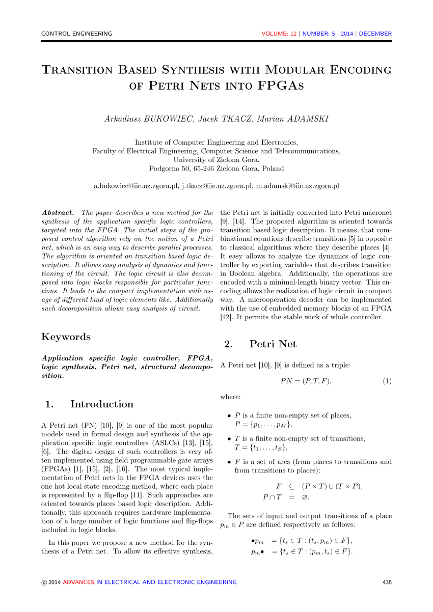
The proposed method of state code presentation targets on area decrease under implementation of Moore FSM logic circuit with customized matrices.